MakerGram Logo

    MakerGram

    • Register
    • Login
    • Search
    • Categories
    • Recent
    • Popular
    • Tags
    • Users
    • Groups

    PCB Design for ESP32 Stand alone module

    PCB Designing
    pcb esp32
    7
    31
    19059
    Loading More Posts
    • Oldest to Newest
    • Newest to Oldest
    • Most Votes
    Reply
    • Reply as topic
    Log in to reply
    This topic has been deleted. Only users with topic management privileges can see it.
    • S
      Sharmila @Sharmila last edited by

      And having one more doubt !
      Bootloader for esp32 will present already or we need to load the bootloader code into the newly brought esp32 chip ?

      1 Reply Last reply Reply Quote 0
      • kowshik1729
        kowshik1729 last edited by

        @Sharmila If you're programming the board for the first time using Arduino IDE then you need to burn the bootloader into the bare IC. I have a doubt when you said the IC is not getting programmed even though the GPIO0 is low.

        I wanna know is GPIO0 low all the time or did you pull it low momentarily using a button??

        S 1 Reply Last reply Reply Quote 0
        • S
          Sharmila @kowshik1729 last edited by

          @kowshik1729 Yes i m programming the board first time using arduion. GPIO 0 is low all the time.

          1 Reply Last reply Reply Quote 0
          • kowshik1729
            kowshik1729 last edited by kowshik1729

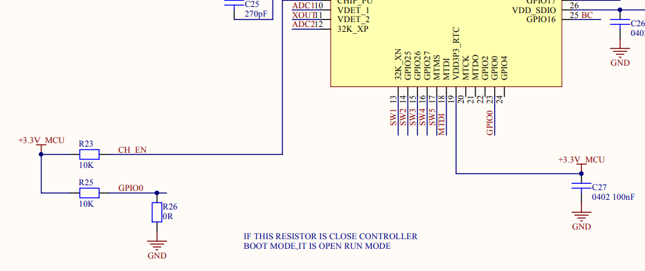
            @Sharmila GPIO0 must not be low all the time. It must be held low only for a moment. Because GPIO0 is a boot strap option for choosing between UART download and normal operation. Please refer to the datasheet and search boot strap. And also can you please post a snap of your newly designed board please?

            S 2 Replies Last reply Reply Quote 1
            • S
              Sharmila @kowshik1729 last edited by Sharmila

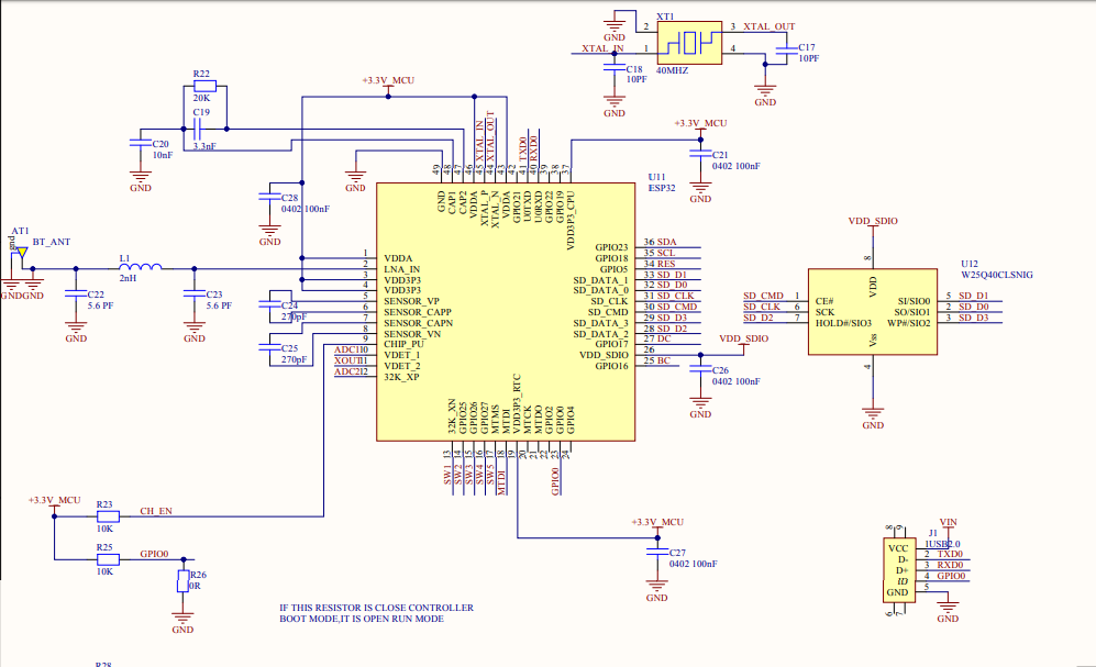
              @kowshik1729 thank you for the hint ! i will check it . schematic picture of my board is given below

              (freesnippingtool.com_capture_20200721122206.png)

              saheen_palayi 1 Reply Last reply Reply Quote 1
              • S
                Sharmila @kowshik1729 last edited by

                @kowshik1729 sorry, gpio 0 is low only till it is programmed. after that this will disconnected.

                1 Reply Last reply Reply Quote 0
                • kowshik1729
                  kowshik1729 last edited by

                  @Sharmila Reviewed your schematics. Have the following doubts

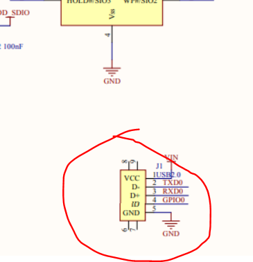
                  1. Is this a USB receptacle?

                  4f585013-72f9-4ceb-bc72-8fa40ff32a36-image.png

                  1. Didn't find any option where you can pull the GPIO0 low and bring it back to normal state. Did you have a jumper connection or button between GPIO0 and GND?
                  1 Reply Last reply Reply Quote 0
                  • S
                    Sharmila last edited by

                    1. no.
                    2. we are using jumper for gpio 0th pin. please refer the below image.
                      freesnippingtool.com_capture_20200721200934.png
                    1 Reply Last reply Reply Quote 0
                    • saheen_palayi
                      saheen_palayi @Sharmila last edited by

                      This post is deleted!
                      1 Reply Last reply Reply Quote 0
                      • First post
                        Last post

                      Recent Posts

                      • A

                        The reason I wanna use online tools only is because, I have been using my company's lappy and I am restricted to install any other Softwares. So, online tools will be an easy way for me. by the way I have found another way too. EasyEDA provides an super easy solution for creating custom PCB shapes. It really came in handy for me.

                        • read more
                      • Hi all,

                        I recently came across this post where they have shown photos printed on PCB in high resolution. I would like to know how to add this kind of photos to the silkscreen layers of the PCB in Eagle/Altium.

                        Adding such kind of photos will be attractive for beginners and also can be used for educational purposes too.
                        Please let me know in case anybody knows.

                        • read more
                      • @kowshik1729 I think that might not get since the platform is not opensource! but they provided everything you need to develop a system with that.

                        • read more
                      • @kowshik1729 Carrier board schematics for SoMs will be always available as they need to be modified as per customer application, however SoM design files are hard to get unless the H/W design is truly open-source.

                        • read more
                      • @salmanfaris Actually the schematics files you've mentioned are the same files which I've got from them. They are carrier board design files.😢

                        • read more
                      By MakerGram | A XiStart Initiative | Built with ♥ NodeBB
                      Copyright © 2023 MakerGram, All rights reserved.
                      Privacy Policy | Terms & Conditions | Disclaimer | Code of Conduct