MakerGram Logo

    MakerGram

    • Register
    • Login
    • Search
    • Categories
    • Recent
    • Popular
    • Tags
    • Users
    • Groups

    PCB Design for ESP32 Stand alone module

    PCB Designing
    pcb esp32
    7
    31
    18901
    Loading More Posts
    • Oldest to Newest
    • Newest to Oldest
    • Most Votes
    Reply
    • Reply as topic
    Log in to reply
    This topic has been deleted. Only users with topic management privileges can see it.
    • kowshik1729
      kowshik1729 last edited by

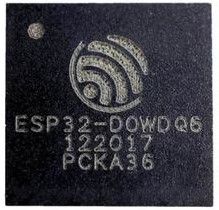
      @salmanfaris thanks for the reply but this is not exactly what I am looking for I think this is the system on chip version of ESP 32 Wroom. There is no LNA circuit connection for antenna part. Please let me know if you find the the appropriate connections for the ESP 32 stand alone chip. To be simple, I want the circuit that we find when the metal part of SoC is removed.

      1 Reply Last reply Reply Quote 0
      • salmanfaris
        salmanfaris last edited by salmanfaris

        @kowshik1729 so you need the SoC minimum config, not the Module right?

        Page No. 18

        Capture.JPG

        ESP32-D0WDQ6__79125.1563952720.jpg

        1 Reply Last reply Reply Quote 0
        • kowshik1729
          kowshik1729 last edited by

          Yes, Exactly. I need PCB layout for something as shown below. The rip opened part.
          8b585816-915b-4dbb-9012-1f4fea88a664-image.png

          1 Reply Last reply Reply Quote 0
          • salmanfaris
            salmanfaris last edited by

            @salmanfaris said in PCB Design for ESP32 Stand alone module:

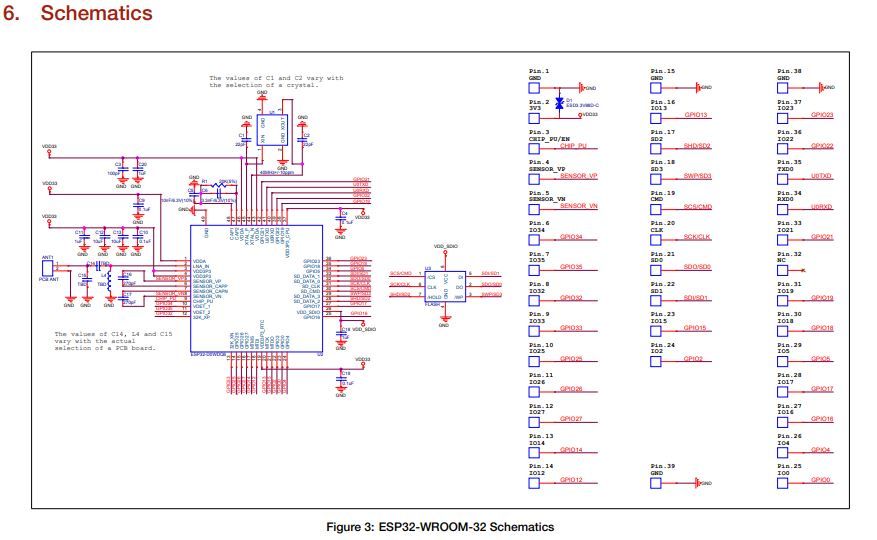
            take a look at the ESP32 wroom datasheet page number 19, they provided a minimum circuit

            If you need the module schematic? the use this.

            1 Reply Last reply Reply Quote 0
            • kowshik1729
              kowshik1729 last edited by

              @salmanfaris Thank you so much. I am exactly looking for SoC minimum config, not the module. Shall ping the forum in case of any hassle.

              salmanfaris 1 Reply Last reply Reply Quote 0
              • salmanfaris
                salmanfaris @kowshik1729 last edited by

                @kowshik1729 Great.

                1 Reply Last reply Reply Quote 0
                • kowshik1729
                  kowshik1729 last edited by

                  @salmanfaris In the figure 3 : ESP32-WROOM-32 Schematics, should I surely use all the capacitors for VDD pins? Are there any redundant connections like these? I want to reduce these unnecessary connections to keep my board size all low as possible. Please suggest how I can optimize the connections?

                  1 Reply Last reply Reply Quote 0
                  • kowshik1729
                    kowshik1729 last edited by

                    @salmanfaris I've got a doubt. Is there a way to program ESP32 without having USB adapter on the board? Something like how we do for ATMega328p. If there is a way like that please let me know..!! Thanks in advance..!

                    1 Reply Last reply Reply Quote 0
                    • salmanfaris
                      salmanfaris last edited by salmanfaris

                      Hi @kowshik1729,

                      Yes, you can. we can programme the esp32 is different methods, and I suggest to use UART like we are using ESP8266, for that you need an FTDI or UART to Serial converter.

                      also make you that before uploading the programme, you need to switch to programme mode, if you share the exact esp32 model, I'll check the modes .

                      Z 1 Reply Last reply Reply Quote 0
                      • kowshik1729
                        kowshik1729 last edited by

                        @salmanfaris I've been looking to use ESP32-PICO D2 for my design. Please let me know the ways to programme it. I am insisting more on avoiding the UART connection because it again needs USB TO UART converter IC like CP2102 etc.. so please let me know if any other ways are there. 😊

                        1 Reply Last reply Reply Quote 0
                        • First post
                          Last post

                        Recent Posts

                        • A

                          The reason I wanna use online tools only is because, I have been using my company's lappy and I am restricted to install any other Softwares. So, online tools will be an easy way for me. by the way I have found another way too. EasyEDA provides an super easy solution for creating custom PCB shapes. It really came in handy for me.

                          • read more
                        • Hi all,

                          I recently came across this post where they have shown photos printed on PCB in high resolution. I would like to know how to add this kind of photos to the silkscreen layers of the PCB in Eagle/Altium.

                          Adding such kind of photos will be attractive for beginners and also can be used for educational purposes too.
                          Please let me know in case anybody knows.

                          • read more
                        • @kowshik1729 I think that might not get since the platform is not opensource! but they provided everything you need to develop a system with that.

                          • read more
                        • @kowshik1729 Carrier board schematics for SoMs will be always available as they need to be modified as per customer application, however SoM design files are hard to get unless the H/W design is truly open-source.

                          • read more
                        • @salmanfaris Actually the schematics files you've mentioned are the same files which I've got from them. They are carrier board design files.😢

                          • read more
                        By MakerGram | A XiStart Initiative | Built with ♥ NodeBB
                        Copyright © 2023 MakerGram, All rights reserved.
                        Privacy Policy | Terms & Conditions | Disclaimer | Code of Conduct