Programming bare ATMega328P(SMD IC) from scratch for custom boards 👨💻
Developing a custom PCB for personalized applications with Atmega328P SMD IC and stuck at how to program it or make it work with Arduino IDE like a normal Arduino UNO? Then you're at the right place.
What is the difference between Arduino UNO and having Atmega328p on custom PCB's?
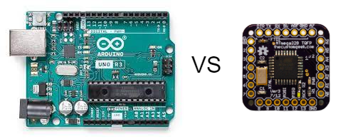
Arduino UNO is completely customized to work as evaluation board for the Atmega328p IC. It has on-board USB to serial converter IC which translates information coming on the USB from your PC to TTL logic that is understood by the MCU. Whereas on your custom boards, USB to serial adapters are usually not present (At least for the designs I make). This is usually done by the designers because AVR microcontrollers like Atmega328p comes with an programming and debug interface called ICSP(In-circuit Serial programming) which just uses 6 pins on the microcontroller to directly upload the code from any external programmers. Now, this is not a very traditional method to use but it reduces the number of parts on the PCB greatly saving few bucks to the designer while mass producing the PCB's.
So do I have to use costly programmers like Atmel ICE or other debuggers to program these custom IC's?
One word answer - NO! Fortunately there are multiple other ways to do it. I am going to discuss the easiest method amongst all those and you don't have to purchase any costly stuff to do this. All you need is
1. Arduino UNO(This is bare minimum requirement to program your custom board)
2. Your custom board with Atmega328p IC on it (Note that, the ICSP headers must be extended out to be hooked up with pins of ICSP pins of Arduino UNO)
3. Few jumper wires to makes connections.
4. Arduino IDE.
That is it..! These are the things you need program your custom board and get it up and running like a normal UNO board.
Great! But how did I end up finding this method and what errors did I face with my custom board before trying this method?
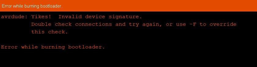
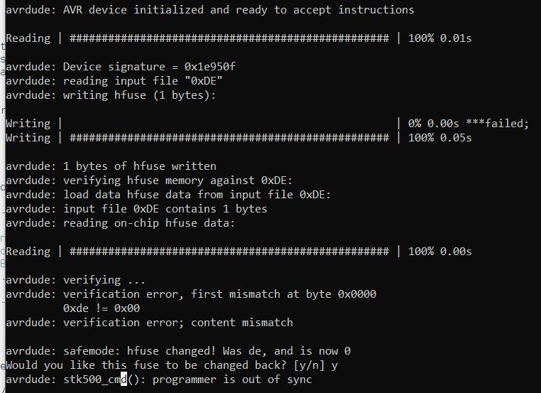
Well, I went through lot of errors trying out different methods out there on the internet failing at every attempt. I have dug so deep such that at one point I was messing up with the fuse bits of the Atmega328p bricking my IC taking it to a state where it no longer accepts any code. However I found a very simple and elegant solution that makes life of hobbyists and makers much more easier. I have faced errors like following
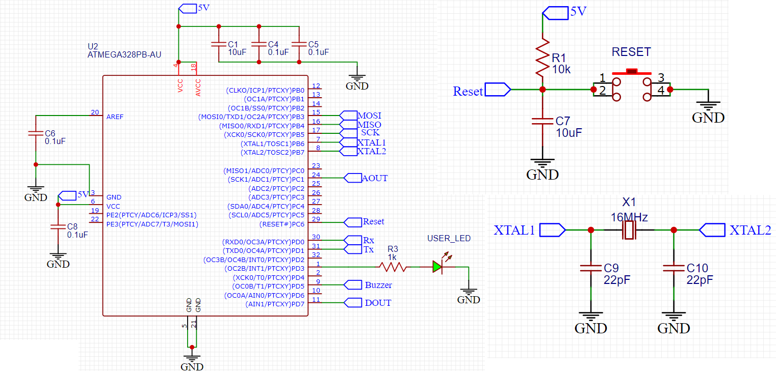
At some point I doubted the schematics that are made for the custom board. I am attaching a snap of my schematics here for your reference to know how the proper schematics must be drawn for the custom boards.
How to program the custom board with Arduino UNO?
The connections to be made between your custom board and Arduino UNO are pretty simple and straight forward. All you have you do is to make straight connections between ICSP pins of both boards as shown below.
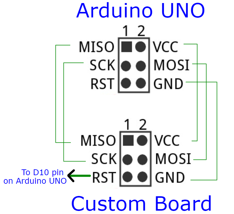
Note that the RST pin of custom board must be connected to D10 pin on the Arduino UNO (Slave select line). Now, open Arduino IDE . Go to
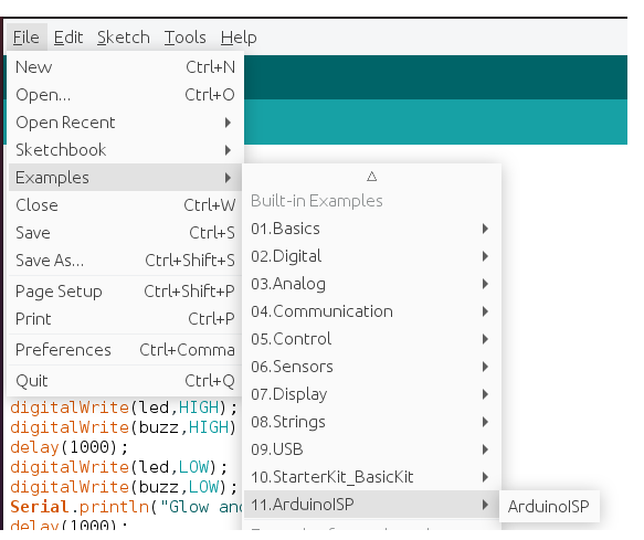
File -> Example -> ArduinoISP -> ArduinoISP sketch
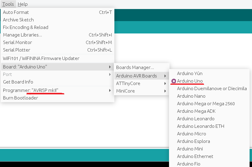
After opening this go to Tools -> Boards -> Arduino UNO. Select programmer as AVRISP mkII.
Now, upload this ArduinoISP sketch to Arduino UNO to convert it as a programmer for your custom board. Once the uploading is done you have successfully converted Arduino UNO as ISP programmer.
Before we proceed with playing around with the custom board, we need to download the proper core files to bootload the IC. To do this,
go to File -> Preferences or press Ctrl + comma on your keyboard.
Paste the following boards link that will help to download and update the boards field of Arduino IDE.
https://mcudude.github.io/MiniCore/package_MCUdude_MiniCore_index.json
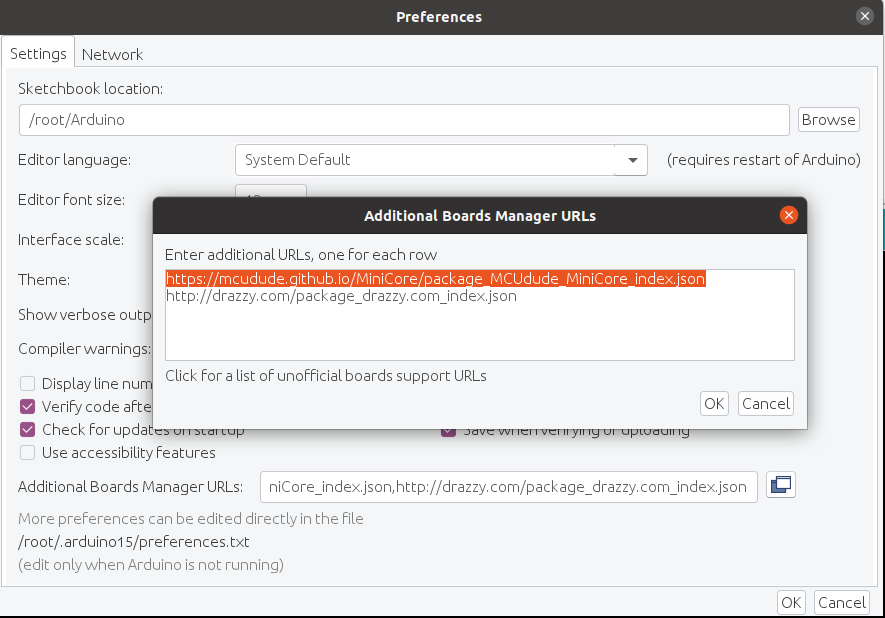
Once it is pasted, click on Ok and exit the window.
Go to Tools -> Boards -> Boards Manager
Find the MiniCore boards file from MCUdude and click on install button to install the boards.
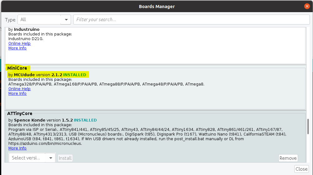
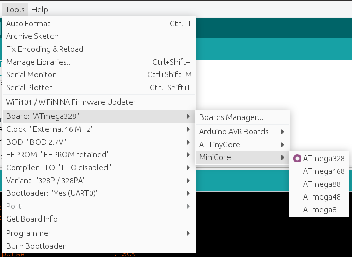
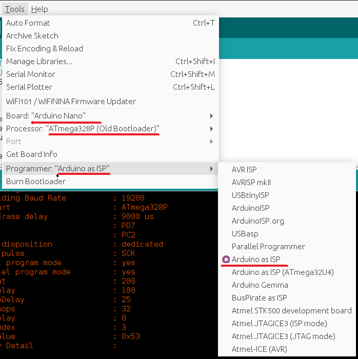
Once this is done, you should be able to see the Atmega328, 168, 88, 48, 8 boards under MiniCore boards section. Select Atmega328p from it as we are using it for the current tutorial. Multiple options will be shown for selecting BOD (Brown out detection), EEPROM, Compiler etc., My suggestion is to leave them as it is and select programmer as Arduino as ISP (minicore) (Important step)
If this programmer is not selected properly then Arduino IDE will not understand through which the path the code must be sent and it gives back an error. Once all the options are properly selected Click on Burn Bootloader option at the end, this will burn the arduino bootloader into the Atmega328p IC which makes it to accept any kind of codes or instruction over ICSP lines.
Once this step is successful it is time to write your own sketches and upload them to the custom board. Open your sketch, go to Tools -> Boards -> Arduino Nano
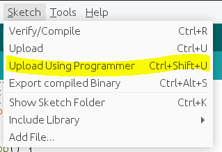
After this step ,finally you need to upload your code using the option
Sketch -> Upload Using Programmer or simply press Ctrl + Shift + U
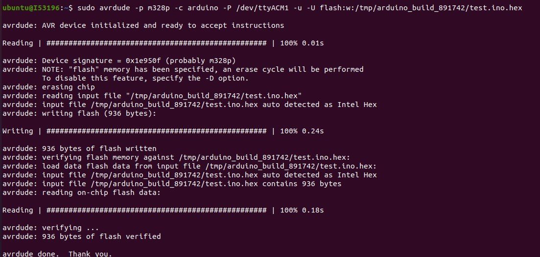
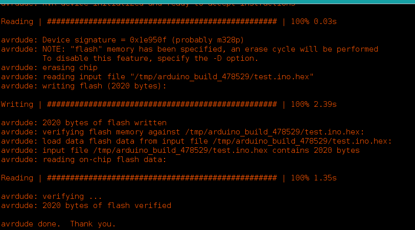
You should see a debug message like shown below which confirms that code is successfully uploaded into your custom board and your board must execute that code.
Thanks for the read. Hope you guys liked it and saved some time for you avoiding the hard work.
Happy Making..!!
Thanks,
Gudimetla Kowshik