Color Terminal 🎨
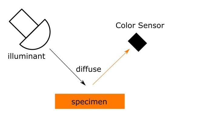
The Color Terminal can be used to pick color from physical things by scanning its surface with Seeed Wio Terminal and TCS34725.
Color Terminal 🎨
A color picker (also color chooser or color tool) is a graphical user interface widget, usually found within graphics software or online, used to select colors and sometimes to create color schemes. (WiKi)
Traditional color picking software can't take color from a physical surface, that's where the color terminal comes to play. It's a device that can take color and provide color code in Hex and RGB values.
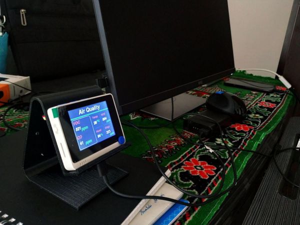
The Color terminal powered by SeeedStudio Wio Terminal and Adafruit RGB Color sensor .
Let's Build 🛠️
Components Required
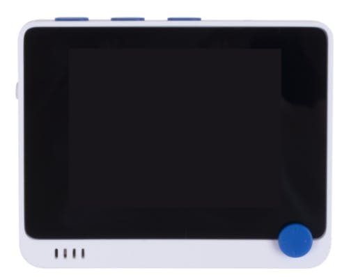
- Wio Terminal: Wio Terminal based on ATSAMD51-based microcontroller with wireless connectivity supported by Realtek RTL8720DN and is equipped with a 2.4” LCD Screen, onboard IMU(LIS3DHTR), Microphone, Buzzer, microSD card slot, Light sensor, and Infrared Emitter(IR 940nm). Realtek RTL8720DN chip supports both Bluetooth and Wi-Fi providing the backbone for IoT projects.
- TCS34725 RGB Color Sensor: The TCS34725, which has RGB and Clear light sensing elements. An IR blocking filter, integrated on-chip and localized to the color sensing photodiodes, minimizes the IR spectral component of the incoming light and allows color measurements to be made accurately. The filter means you'll get much truer color than most sensors since humans don't see IR. The sensor also has an incredible 3, 800, 000:1 dynamic range with adjustable integration time and gain so it is suited for use behind darkened glass.
Steps Required
- Connect TCS34725 RGB Color Sensor to Wio Terminal with Adpater board or Breadboard
- Upload the Color Terminal sketch to wio terminal.
- Start Scanning.
Seeed Wio Terminal
The Wio Terminal based ATSAMD51-based microcontroller with wireless connectivity supported by Realtek RTL8720DN and is equipped with a 2.4” LCD Screen, onboard IMU(LIS3DHTR), Microphone, Buzzer, microSD card slot, Light sensor, and Infrared Emitter(IR 940nm). Realtek RTL8720DN chip supports both Bluetooth and Wi-Fi providing the backbone for IoT projects.
Key Features
- Powerful MCU: Microchip ATSAMD51P19 with ARM Cortex-M4F core running at 120MHz
- Reliable Wireless Connectivity: Equipped with Realtek RTL8720DN, dual-band 2.4Ghz / 5Ghz Wi-Fi
- Highly Integrated Design: 2.4” LCD Screen, IMU and more practical add-ons housed in a compact enclosure with built-in magnets & mounting holes
- Raspberry Pi 40-pin Compatible GPIO
- Compatible with over 300 plug&play Grove modules to explore with IoT
- USB OTG Support
- Support Arduino, CircuitPython, Micropython, ArduPy(What is ArduPy?), AT Firmware, Visual Studio Code
- TELEC certificated
For more information go to https://www.seeedstudio.com/Wio-Terminal-p-4509.html.
Step 1: Setup Wio Terminal
For Setup, you can follow this wonderful guide provide by SeeedStudio. Get Started with Wio Terminal, anyway I'll go through quickly.Step 1.1: Download and Install the Arduino IDE: We are using Arduino IDE to programme the Wio Terminal, so we need to install it on our computer first. Click here to download Arduino IDEStep 1.2: Install Wio Terminal: Arduino IDE comes with official boards loaded from the Arduinio.cc so In order to program Wio Terminal we need to install the Wio Terminal Board packages and definition on the Arduino IDE.1.2.2: Add Additional Boards Manager URL: For that Open your Arduino IDE, click on File > Preferences, and copy below URL to Additional Boards Manager URLs
https://files.seeedstudio.com/arduino/package_seeeduino_boards_index.json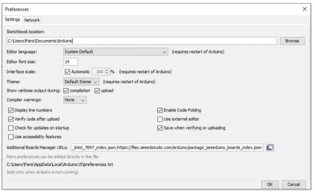
Note: If you have more additional boards manager URL's like me, make it separate with commas.
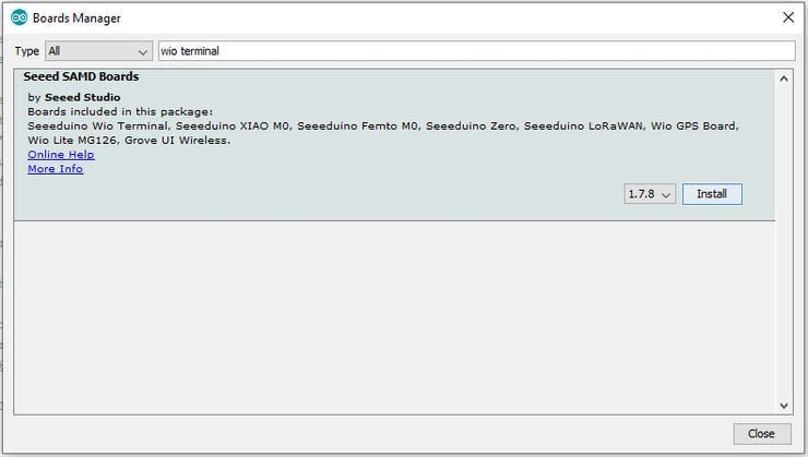
1.2.3: Install Wio Terminal Board Manager: For that Click on Tools > Board > Board Manager and Search Wio Terminal in the Boards Manager.
1.2.4: Select your board and port: For that, you'll need to select the entry in the Tools > Board menu that corresponds to your Arduino. Selecting the Wio Terminal.
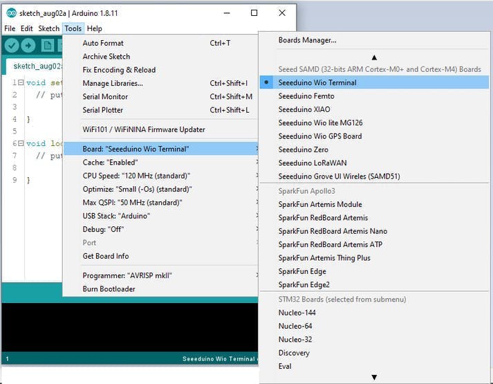
Select the serial device of the Wio Terminal board from the Tools -> Port menu. This is likely to be COM3 or higher (COM1 and COM2 are usually reserved for hardware serial ports). To find out, you can disconnect your Wio Terminal board and re-open the menu; the entry that disappears should be the Arduino board. Reconnect the board and select that serial port.
RGB Color Sensor with IR filter and White LED - TCS34725
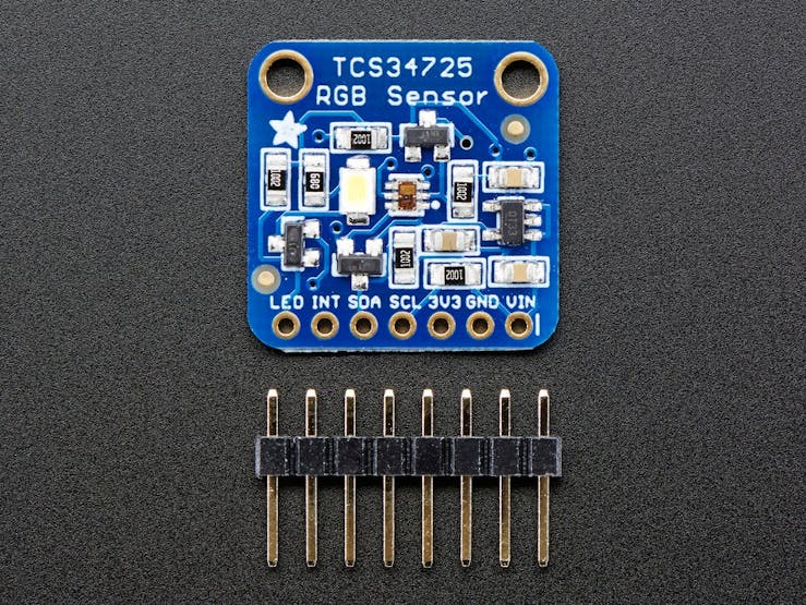
The TCS34725 has RGB and Clear light sensing elements. An IR blocking filter, integrated on-chip and localized to the color sensing photodiodes, minimizes the IR spectral component of the incoming light and allows color measurements to be made accurately.
The filter means we will get much truer color than most sensors, since humans don't see IR. The sensor also has an incredible 3, 800, 000:1 dynamic range with adjustable integration time and gain so it is suited for use behind darkened glass.Features
- Red, Green, Blue (RGB), and Clear Light Sensing with IR Blocking Filter
- Programmable Analog Gain and Integration Time
- Maskable Interrupt (Programmable Upper and Lower Thresholds with Persistence Filter)
- Power Management:Low Power — 2.5-A Sleep State − 65-A Wait State with Programmable Wait State Time from 2.4 ms to > 7 Seconds
- I2C Fast Mode Compatible Interface − Data Rates up to 400 kbit/s
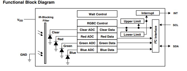
The TCS3472 light-to-digital converter contains a 3 × 4 photodiode array, four analogue-to-digital converters (ADC) that integrate the photodiode current, data registers, a state machine, and an I2C interface.The 3 × 4 photodiode array is composed of red-filtered, green-filtered, blue-filtered, and clear (unfiltered) photodiodes. In addition, the photodiodes are coated with an IR-blocking filter.
The four integrating ADCs simultaneously convert the amplified photodiode currents to a 16-bit digital value. Upon completion of a conversion cycle, the results are transferred to the data registers, which are double-buffered to ensure the integrity of the data. All of the internal timing, as well as the low-power wait state, is controlled by the state machine.Adaruit provides a good library to work with the arduino and it supports wio terminal too.
Step 2: Setup TCS3472
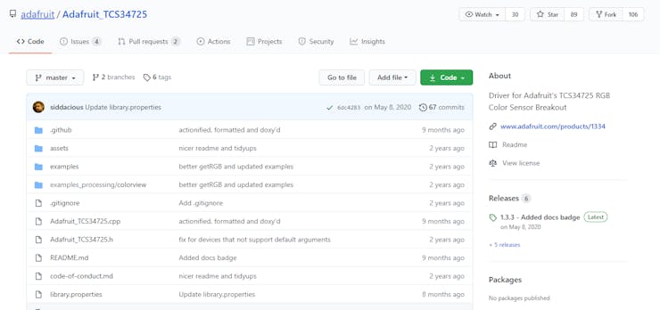
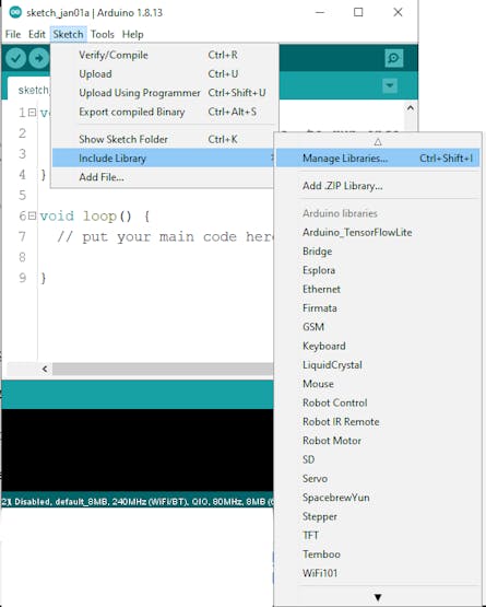
First, we need to set up the TCS3472 for the Wio TerminalStep 2.1: Download and Install Arduino Librariesopen up the Manage Libraries in Arduino IDE from Sketch -> Include Library -> Manage Libraries.
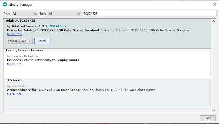
Then search for Adafruit TCS34725 and click Install.
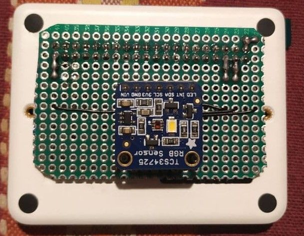
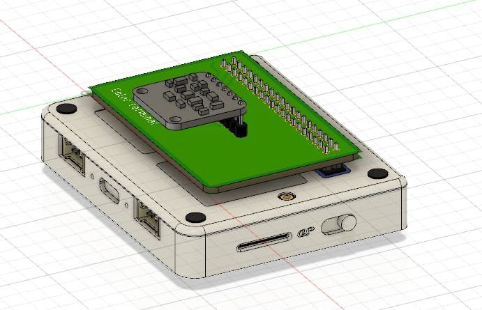
Step 3: Build a Sensor Adapter Board.
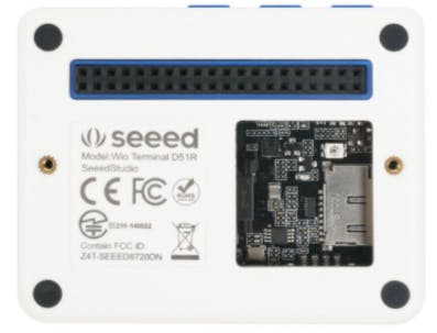
The wio terminal comes with a 40-pin pinout.
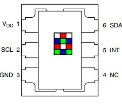
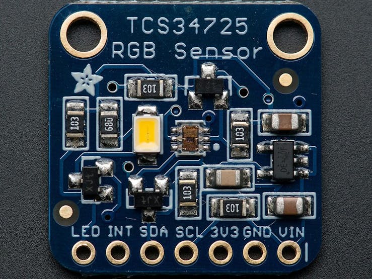
and the TCS34725 comes with the 7 pin breakout.
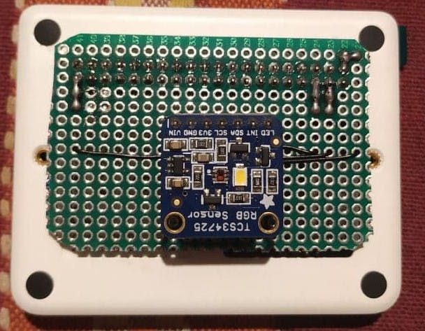
We need to make an adapter board in order to easily connect the wio terminal and TCS34725 sensor breakout.
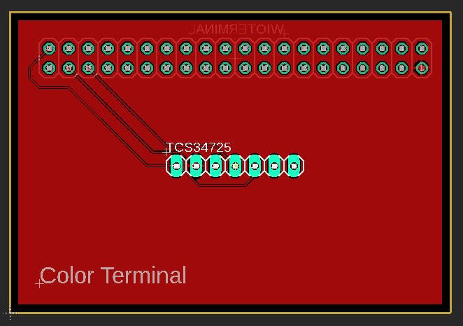
Step 3.1: Design Adapter Board.
PCB
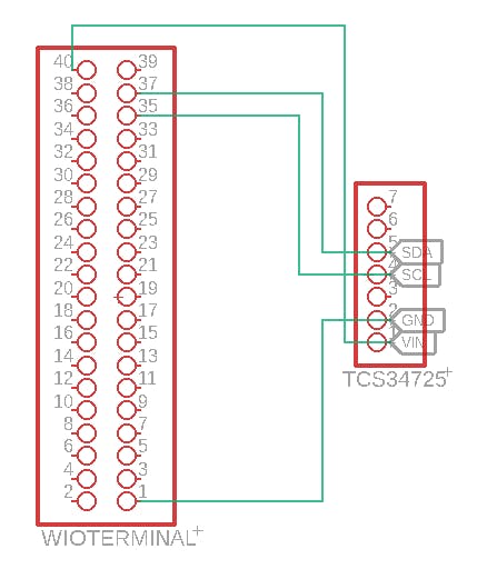
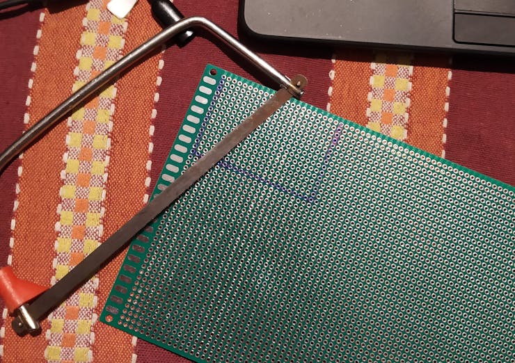
You can build the addon board using generic perf board.
Perfboard MethodFirst, mark the dimensions
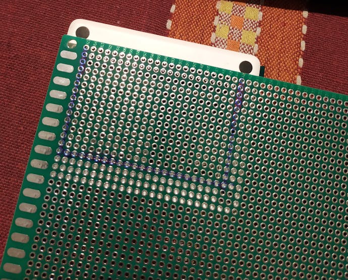
Cut through the dimensions
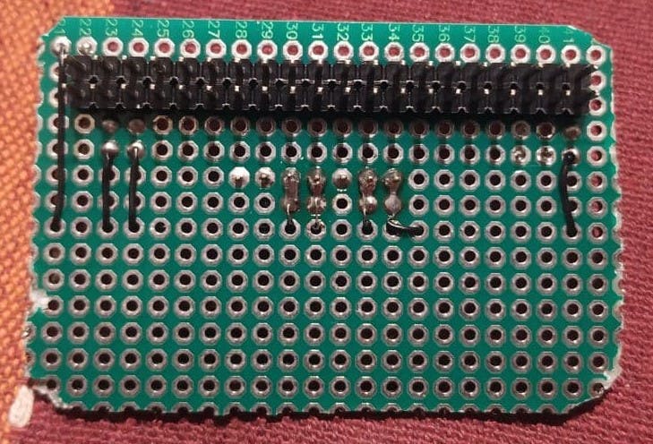
Solder the pins.
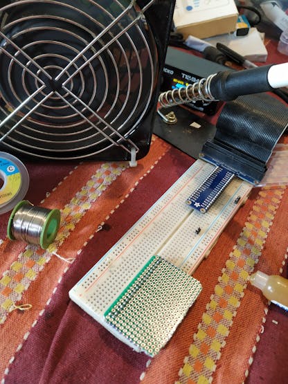
I used wire wrapping wire to make the connection between the 40 pins and the sensor breakout.
Step 4: Upload Arduino Sketch
/*
 * Author : Salman Faris
 * Project : Color Terminal
 * Date: 01/01/2021
 */


#include <Wire.h>
#include "Adafruit_TCS34725.h"
#include"TFT_eSPI.h"

TFT_eSPI tft;
TFT_eSprite spr = TFT_eSprite(&tft);  //sprite
#define TFT_GREY 0x5AEB // New colour

float red, green, blue;
String Hex = "#000000";

// our RGB -> eye-recognized gamma color
byte gammatable[256];

Adafruit_TCS34725 tcs = Adafruit_TCS34725(TCS34725_INTEGRATIONTIME_101MS, TCS34725_GAIN_60X);

void setup() {

  tft.begin();
  tft.setRotation(3);

  //Head
  tft.fillScreen(TFT_GREY);
  tft.setFreeFont(&FreeSansBoldOblique18pt7b);
  tft.setTextColor(TFT_WHITE);
  tft.setCursor(55, 120);
  tft.print("Wio Terminal ");
  tft.setCursor(55, 160);
  tft.print("Color Picker");
  delay(3000);
  tft.fillScreen(TFT_GREY);

  red = 0;
  green = 0;
  blue = 0;


  pinMode(WIO_KEY_B, INPUT_PULLUP);
  Serial.begin(9600);
  //Serial.println("Color View Test!");

  if (tcs.begin()) {
    //Serial.println("Found sensor");
  } else {
    Serial.println("No TCS34725 found ... check your connections");
    while (1); // halt!
  }

  // thanks PhilB for this gamma table!
  // it helps convert RGB colors to what humans see
  for (int i = 0; i < 256; i++) {
    float x = i;
    x /= 255;
    x = pow(x, 2.5);
    x *= 255;

    //      if (commonAnode) {
    //gammatable[i] = 255 - x;
    //      } else {
    gammatable[i] = x;
    //      }
    Serial.println(gammatable[i]);
  }
}

void loop() {


  delay(60);  // takes 50ms to read
  if (digitalRead(WIO_KEY_B) == LOW) {

    tcs.getRGB(&red, &green, &blue);
    Serial.print("R: \t"); Serial.print(int(red));
    Serial.print("\tG: \t"); Serial.print(int(green));
    Serial.print("\tB: \t"); Serial.print(int(blue));

    tft.fillScreen(tft.color565(gammatable[(int)red], gammatable[(int)green] , gammatable[(int)blue]));
    Serial.print("\t");
    Serial.print((int)red, HEX); Serial.print((int)green, HEX); Serial.print((int)blue, HEX);
    Serial.print("\n");
  }
  else {
    Serial.println("IDLE STATE ");

    spr.createSprite(65, 30);
    spr.fillSprite(TFT_RED);
    spr.setFreeFont(&FreeSansBoldOblique12pt7b);
    spr.setTextColor(TFT_BLACK);
    spr.drawNumber(int(red), 10 , 0, 1);
    spr.pushSprite(65 , 5);
    spr.deleteSprite();

    spr.createSprite(65, 30);
    spr.fillSprite(TFT_GREEN);
    spr.setFreeFont(&FreeSansBoldOblique12pt7b);
    spr.setTextColor(TFT_BLACK);
    spr.drawNumber(int(green), 10 , 0, 1);
    spr.pushSprite(130 , 5);
    spr.deleteSprite();

    spr.createSprite(65, 30);
    spr.fillSprite(TFT_BLUE);
    spr.setFreeFont(&FreeSansBoldOblique12pt7b);
    spr.setTextColor(TFT_BLACK);
    spr.drawNumber(int(blue), 10 , 0, 1);
    spr.pushSprite(195 , 5);
    spr.deleteSprite();


    String Rhex = String((int)red, HEX);
    String Ghex = String ((int)green, HEX);
    String Bhex = String ((int)blue, HEX);
    Hex = '#' + Rhex + Ghex + Bhex;

    spr.createSprite(195, 30);
    spr.fillSprite(TFT_GREY);
    spr.setFreeFont(&FreeSansBoldOblique12pt7b);
    spr.setTextColor(TFT_WHITE);
    spr.drawString(Hex, 50 , 0, 1);
    spr.pushSprite(65 , 35);
    spr.deleteSprite();


  }
}
Copy the code into Wio Terminal and upload. If you do not know how to upload the code, please check how to upload code.
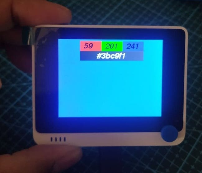
Step 5: Run.
To start colour scan you need to press 'B' button,
Next step
- The system needs to improve further ore in order to produce the color more accurately
- Build 3D Printed Case
- Add Color hue on display